Introduction
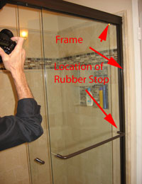
Traditional sliding tempered glass doors, such as those used for patio doors and shower enclosures, moved inside an enclosed frame. These doors were suspended on rollers that rolled inside a “groove”; all of this was hidden by a frame. These doors stopped against a rubber “bumper”, also hidden in the frame. The door stopped when it ran into the bumper located halfway up the door. The dominant stopping force associated with stopping occurs when the edge of the door impacts the rubber stop (i.e. bumper). Another design is to have the tempered glass door hanging off rollers that ride on a circular rail (i.e. pipe). This design often has a rubber stop on the upper rail. When the door stops there are forces transmitted to the hanger bolts due to a moment generated when the free swinging door hits the stop on the top, and the momentum of the door bottom “wrenches “ the door.
Results Summary
All the doors failed when in the process of stopping. Failure analysis of the doors determined that the failures initiated in one of the hanger through holes. It is believed that the torque moment created by the free moving door bottom created enough force on the hole to cause failure. The way to correct this problem is to reduce the forces by slowing the door down while it is stopping, or reduce “stopping” torque by putting the rubber stop in the middle of the door.
Objective
Perform a failure analysis to determine why the doors fail upon closing. Use the results of the failure analysis to devise potential improvements that will eliminate the breaking.
 |
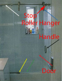 |
Figure #1: Examples of the two types of sliding tempered glass doors discussed in the introduction.
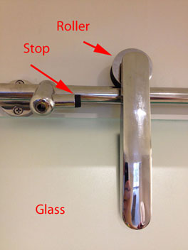
Figure #2: Close-up of the top of a frameless shower door that shows the roller and one of the stops. Although it is a rubber stop the swinging of the door bottom generates high forces that can cause the door to fail.
Results
The failures initiate on the inner walls of the glass hanger holes. This particular failure initiated at the hole labeled #2. When the hardware on the top of the glass hit the stop, the torque (i.e. twisting) of the door created enough force to cause failure.
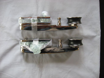
Figure #3: Photograph of the two roller assemblies, as received, from one failed roller door.
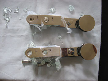
Figure #4: Photograph of the two rollers during disassembly. The failure origin was found to be located at bolt #2.
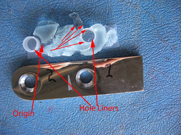
Figure #5: Photograph of the two through holes after the cover plate has been removed. The location of the failure origin is indicated. The failure originated on the side wall of the through hole for bolt #2. The small arrows show the direction of travel of the initial crack.
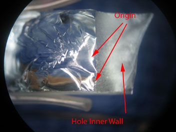
Figure #6: Photomicrograph of the failure origin. There were two origins located on the inner wall of hole #2 (Mag. 4X).
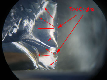
Figure #6: Higher power photomicrograph of the failure origin. There were two origins located on the inner wall of hole #2 (Mag. 6X).


