


Introduction
A failure analysis was performed on a polypropylene Adirondack lawn chair that had collapsed. The subject chair failed during expected normal use when a 190 pound man sat in it.
Procedure
The failed plastic lawn chair was evaluated visually. In addition, the fracture surfaces were examined with a low power microscope.
Root Cause Failure Analysis: Result Summary
Please refer to the photographs below for the failure analysis results.
|
|
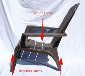
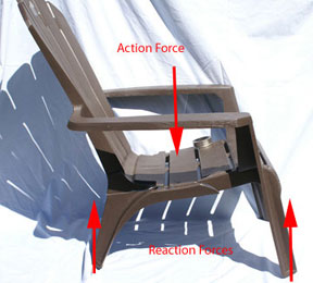
Figure #1: Two views of the failed plastic lawn chair. The failed leg is seen in the photograph on the right.
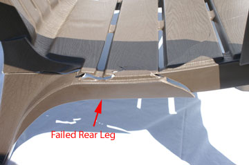
Figure #2: Close up of the failed leg on the right side of the chair. The chair was re-assembled to demonstrate the location of the failure. The chair’s right leg “splayed” out (i.e. bent outwards) and broke off in a brittle manner.
 |
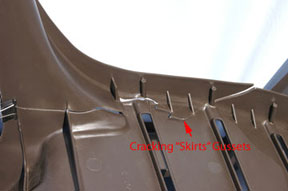 |
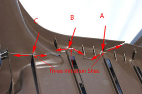
Figure #3: Photograph of the underside of the chair showing the failed leg. Please note that there are three failure origins. The photograph on the right shows that the traveling crack “skirts” the re-enforcing gussets. Two of the origins (A & B) are associated with cylindrical artifacts attached to the underside of the seat and the side wall of the leg (mini gussets?). It is believed that the failure was sequential beginning at origin ‘A’.
|
|
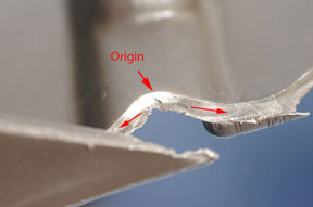
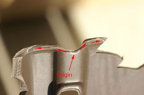
Figure #4: Close ups of plastic failure origins A & B. These are the half of the plastic fracture surface remaining on the chair.
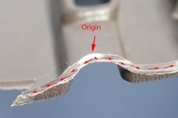
Figure #5: Close up photograph of failure origin ‘B’. This photograph shows the brittle nature of the fracture surface. In addition, it demonstrates clearly that this part of the failure is emanating from the origin. In addition, the crack is driven by bending forces from the inside out.
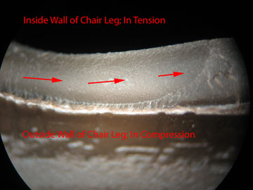
Figure #6: Photomicrograph of the right side of the plastic fracture surface shown in Figure #5 (i.e. near origin B). This shows a crack arrest line; its shape demonstrates that the leg failed due to outward bending. This is a brittle fracture (Mag. 20X)
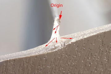
Figure #7: Close up photograph of failure origin ‘C’. This part of the fracture initiated at a very small gusset. It is believed that this is the final break as the leg finally collapses. The final part of the failure is very straight.