


Failure Analysis: Manufacturing Engineer Examines the Root Cause of Automobile Rear View Mirror Failures
The root cause of the failure of customer returns of heated automobile rear view mirrors was investigated.
Theory: Glass fracture theory suggests that the condition of the glass surface is the dominant factor. Theoretically, glass should fail at 1 million pounds per square inch (PSI). In reality, the failure stresses are measured in the range from 2500 to 30,000 PSI. These values are much lower than the theoretical strength, and their variation is quite broad. The explanation for this behavior is that the strength is controlled by surface defects.
Description: The mirrors in this study are heated from the backside to remove snow and ice, and they showed a peak in customer returns in the winter months. This is the time the mirror heater is heavily used. Since the mirror is heated from its backside; the front surface is put in tension and causes the failures. The mirrors in question have a convex curvature that is put into the coated glass before it is “scribed and broken” to size. The scribing operation occurs on the front surface (i.e. on the coated surface). The scribing operation is effected by driving a hard carbide wheel on the coated glass surface. The wheel creates a damage perimeter in the shape of the mirror. This damage is driven through the glass thickness to separate the mirror from the glass sheet. The start point of the scribing operation is critical, and if not done properly, the wheel can cause a “crush” point.
Analysis: A failure analysis was performed on samples of these mirrors to determine the cause of failure. Figure #1 is a sample of a failed mirror. It has a horizontal crack in the middle that goes across the entire mirror.
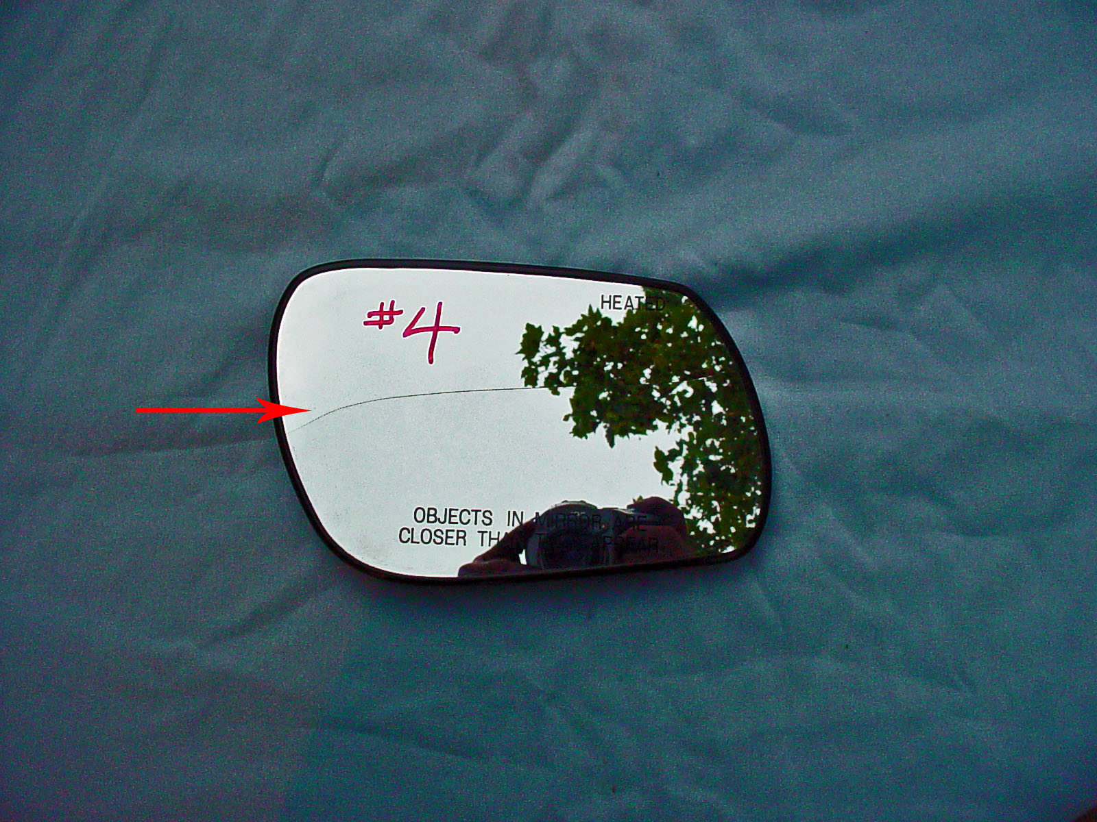
Figure #1: Photograph of a representative cracked mirror. The horizontal crack traverses it just below the “4”. The crack is indicated by the arrow.
Failure analysis revealed that these failures resulted from a “crush” that occurred at the scribe “start” point (Figure #2). Because the height of the curved mirror surface is variable, the scribe wheel hits the surface too hard in some instances. The resulting impact from the scribe tool causes the crush.
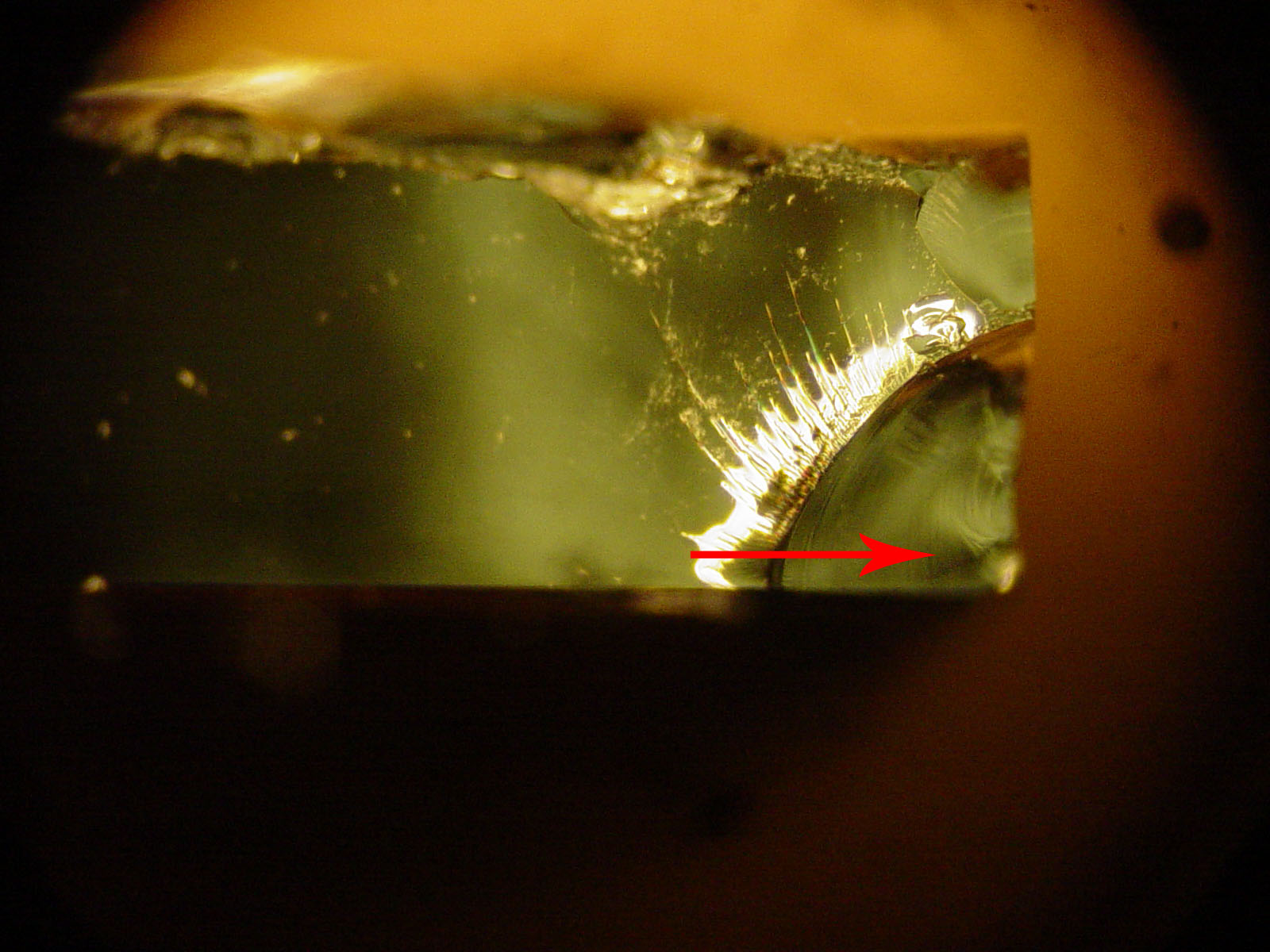
Figure #2: Photomicrograph of a typical crack initiation point. The crack originated at a crush point seen on the lower right corner. The coated side of the mirror is on the bottom of the photograph (Mag. 30X).
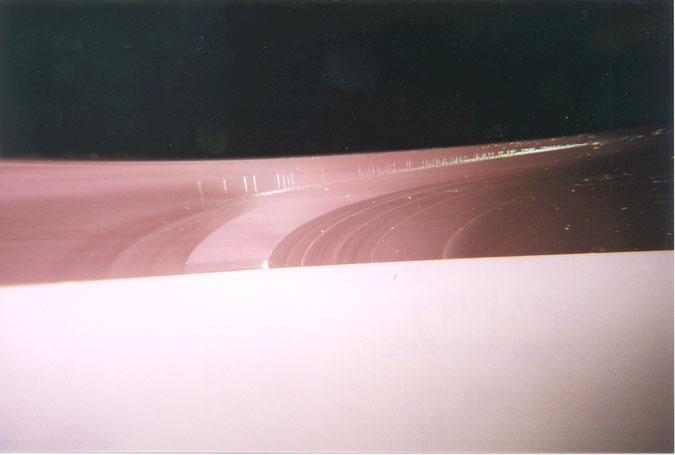
Figure #3: Photomicrograph some of the Wallner lines on the same crack shown in Figure #1.. The crack travels from right to left The coated side of the mirror is on the bottom of the photograph (Mag. 20X).
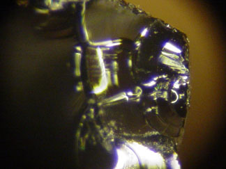
Figure #4: Higher magnification photomicrograph of a representative crush found at the failure origin (Mag 200X)
Crush
Note: The following photographs are of the edges of newly scribed and broken mirrors. They have not failed. A later failure would be a crack separating the piece in at the point of the scribe start. The crack would go into the photograph and away from the reader. In these photographs, the coated surface is at the top of the photograph.
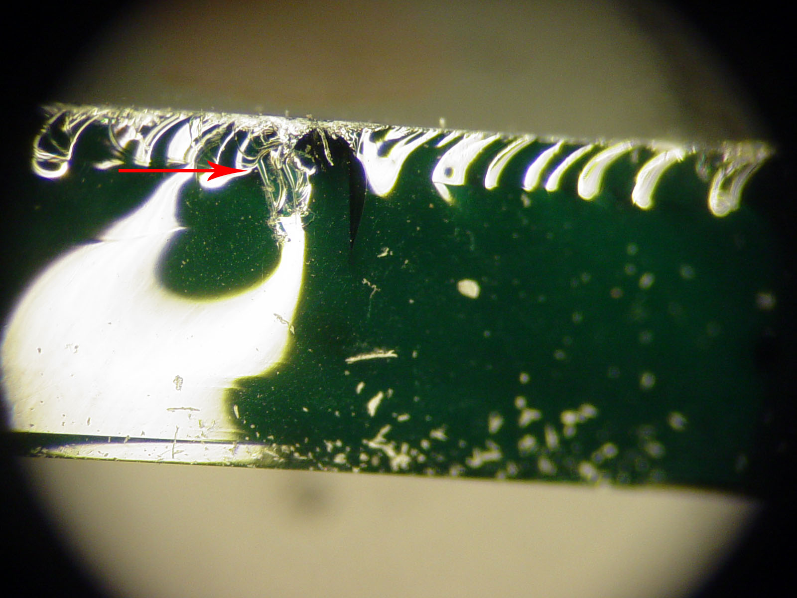
Figure #5: Start point on a new mirror that shows a crush at the top of the starting point. The starting point is on the top of the “winged” shaped crack in the middle of the picture. The arrow indicates the crush (Mag 30X).
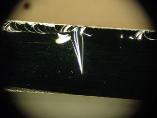
Figure #6: Start point on a mirror that has no crush at the top of the starting point. The starting point is on the top of the “winged” shaped crack in the middle of the picture (Mag. 30X).
Conclusion: The delayed cracking of these rear view mirrors was caused by thermal tensile stresses generated by the backside heater that acted on a weak spot on these mirrors. The weak spot is a “crush” caused by the scribe wheel when it hit the glass surface to start the scribing process. The crush is a scribe process defect that can be eliminated with adjustment of the process.