Introduction
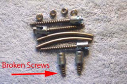
Read Consulting was engaged to determine the cause of failure of two surgical screws which were an integral part of a surgical implant back support system. These two surgical screws are made from titanium, aluminum, vanadium alloy, and their dimensions are 6.5 mm Diameter and 40 mm long.
Results Summary
Both failures are attributed to fatigue in bending that initiated at the screw’s minor diameter. One failure initiated at what appears to be a “machining” or “turning” mark on the minor diameter. The other failure initiated at a very similar location, but there is no visible machining mark. In addition, it is believed that the bending stress on these surgical screws was increased because they were not screwed completely in.
Objectives
Perform a root cause failure analysis of two surgically implanted screws.
Procedure
Scanning Electron Microscope (SEM) with Energy Dispersion Spectroscopy (EDS): Determine the general composition of the subject screws.
Low Power Microscope: Examine and document the two screws using a low power microscope. This includes examining the two fracture surfaces and the condition of the threads at or near the failure initiation sites.
Results
 |
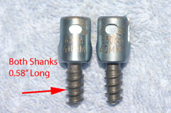 |
Figure #1: Photograph of the two broken surgical implant screws that are the focus of this report. The remaining length of both broken screws is 0.58”.
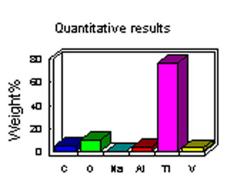
Figure #2: Representative elemental data determined with an SEM with EDS spectroscopy. From this one can see that titanium (Ti) is the parent metal in this alloy. The Ti is alloyed with aluminum (Al) and vanadium (V). The carbon (C), oxygen (O) and sodium (Na) are thought to be surface contaminants.
 |
 |
| Sample A | Sample B |
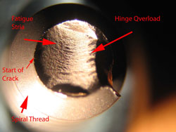
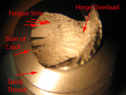
Figure #3: Photomicrographs of the fracture surfaces of the two failed screws. Both screws failed in bending fatigue. This is demonstrated by the fatigue striations (i.e. fatigue “beach marks”) on the initiation part of the both fracture surfaces. As a result of fatigue, the crack grew to the point that the applied bending forces could cause final bending overload failure (Mag. 20X).
 |
 |
| Sample A | Sample B |
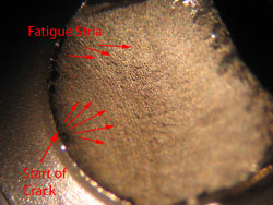
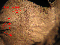
Figure #3: Higher power photomicrographs of the fatigue portion of the fracture surfaces of the two failed screws. Both failures initiated as fatigue cracks. Fatigue is a progressive failure in which the crack grows incrementally each time the bending motion puts the crack tip in tension. (Mag. 40X).
 |
 |
| Sample A | Sample B |
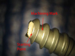
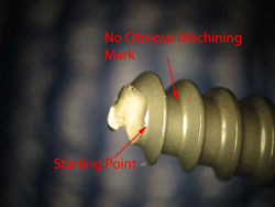
Figure #3: Photomicrographs of a side view of the fracture surfaces of the two failed screws. Both failures initiated as fatigue cracks at the root of the screw threads. For sample ‘A’ the crack appears to have initiated at a machining mark from the threading operation. The sample ‘B’ failure initiated at a similar location, but there is no obvious mark. It appears that these screws have been deburred, and this would tend to eliminate surface marks (Mag. 8X).
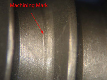
Figure #2: Photomicrograph of the threads on sample A. This is of the threads away from the fracture, and it demonstrates the visible machine mark on sample A. The machining mark can act as a “stress riser” by magnifying the applied stress (Mag. 40X).


