Failure Analysis of a Plastic Lawn Chair
Introduction
A failed plastic lawn chair was examined to determine the cause of failure. This chair failed on the premises of a restaurant In this study the subject chair is examined and compared to several exemplar purchased at the same time. The objective of this study is to determine the cause of failure.
Summary Conclusion
This chair failure was a result of a design defect. The design of the leg and its attachment to the seat create a high stress situation that generated cracks between the leg and the seat.
Procedure
The subject was examined visually and with a low power microscope. In addition, a scanning electron microscope (SEM) was used to examine the fracture surface. The type of plastic was determined using Fourier Transform Infra-red Analysis (FTIR)
Chair Inspections
Subject Chair
Overview
The subject chair is shown Figure #1. The right leg of has separated from the side of the seat. There was no additional damage to the chair, and it doesn’t show signs of significant UV degradation (i.e. all the surfaces remain shiny).
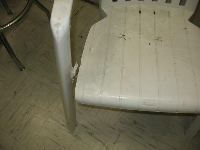
Separation
Figure #1: Photograph of subject chair. The right leg separated from the seat; there appears to be no other significant damage to the chair.
Fractography of the Subject Failure
Both low power and SEM examination of the fracture surfaces indicate a form of low cycle fatigue. There are crack arrest lines perpendicular to the crack travel direction.

Crack Arrest Lines
Figure #2: SEM Photo micrograph of subject fracture. Visible are what are considered crack arrest lines (or fatigue striations) formed during progressive failure of the chair. This is a progressive failure initiating at the top and working its way down through the leg/seat connector.
Examination of Exemplars
At the time of the site inspection all the chairs with the same design as the subject chair had at least one leg with an initial defect that was identical to the one that caused the failure of the subject chair. Three exemplars were removed from the premises for further examination. The initial defect appears as a “dirt line” where the leg is attached to the seat (Figure #3). Examination with an eye loop showed this “line” to be a starting crack (Figure #4). The legs of the exemplars had not separated from the seat; therefore, the mode of failure is progressive.
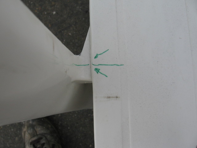
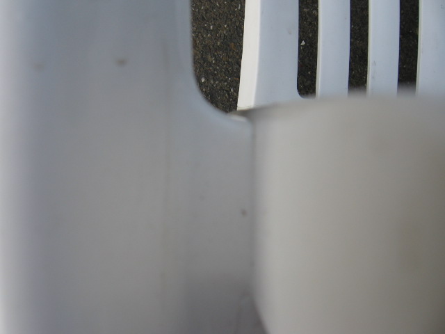
Top View Front View
Figure #3: Photographs of representative defect found on all the chairs inspected. Visually, the defect appears to be a line of dirt in the crevice formed where the leg is attached to the seat. It is also important to note the sharp radius where the leg attaches to the seat (indicated by the arrow). This is where the crack starts.
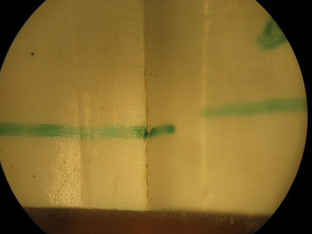
Figure #4: Close up of representative defect found on all the chairs inspected. This is a 4X magnification. It shows the line to actually be a “starting” crack.
The areas of interest for the exemplars were cross-sectioned. Figure #5 shows that the crack has just started, and it does start where the leg is attached to the seat. Also, the thin sections shown in Figure #6 indicate that there is significant separation of pigment ant plastic in the region of interest. The crack initiated at this location as a result of the stress riser caused by the sharp corner. In addition, there was material separation as a result of the flow pattern in this region.
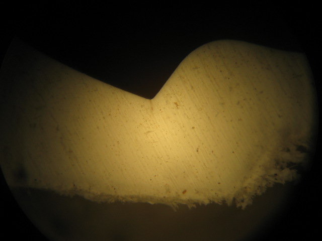
Figure #5: Photo micrograph of one cross section of a representative defect found by examining an exemplar. In this instance the crack is just starting, and it has initiated where the leg is attached to the side of the seat (Mag 16X).
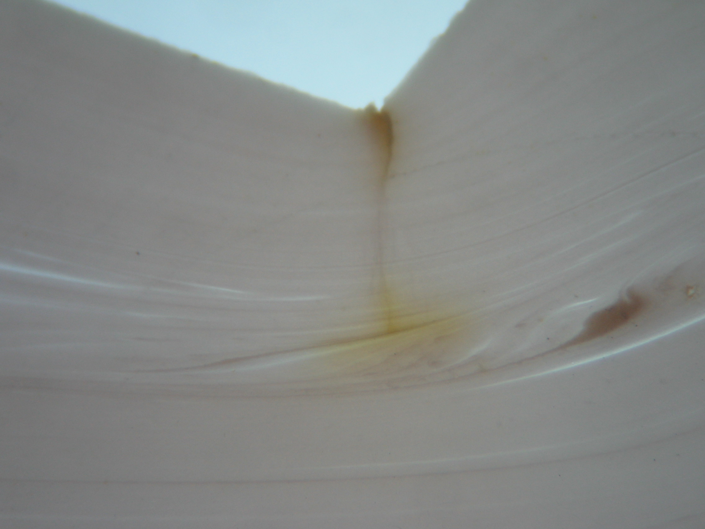
Figure #6: Photo micrograph of one cross section of a representative defect found by examining an exemplar. Before the the cross-sectioning the defect was stained with iodine; in addition it is thinned down and viewed with transmitted light. The Iodine Penetrant indicates that the crack stops midway.
Discussion
The design of these chairs makes them prone to failing. First the sharp corner where the leg attaches to the side of the seat creates a stress riser. In addition the leg pivots about this vulnerable hinge. There is no additional sideways support for the leg. This is best seen by comparing this design with a competitive design.
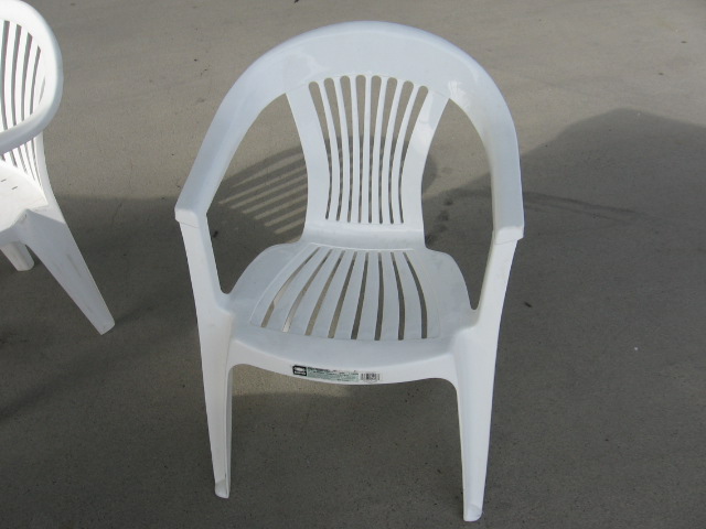
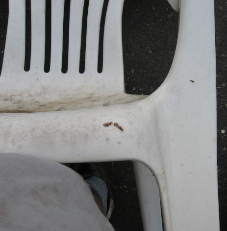
Overview Close Up of Leg/Seat Connection
Figure #7: Alternate design for plastic lawn chairs. One can see that the radius of the intersection of the leg to the seat is much larger. In addition, the “triangular” shape of the leg provides significantly higher support to side loads.


